Decentralized Stability Certificates in IBR-Dominated Grids: The Role of the Network State
Pith reviewed 2026-07-03 08:08 UTC · model grok-4.3
The pith
Reactive power mismatches and line loading impose stricter limits on inverter droop gains for small-signal stability.
A machine-rendered reading of the paper's core claim, the machinery that carries it, and where it could break.
Core claim
We show that increased steady-state reactive power mismatches and line loading lead to more stringent conditions on admissible inverter droop gains. These results make decentralized stability certificates explicitly network-state dependent, showing how network stress shrinks the set of stabilizing local controller parameters.
What carries the argument
A network model that jointly maps reactive power mismatches, line loading, and inverter droop gains to small-signal stability margins.
If this is right
- Higher reactive mismatches force lower droop gains to maintain stability.
- Line loading above certain thresholds further restricts admissible local control parameters.
- Stability certificates must incorporate the prevailing network state rather than fixed bounds.
- Network stress directly reduces the volume of the stabilizing parameter set for each inverter.
Where Pith is reading between the lines
- Real-time estimation of mismatches and loading would be needed to apply the certificates online.
- Adaptive droop tuning could restore margins when the network state changes.
- The same dependence may appear in other small-signal phenomena such as voltage oscillations under high loading.
Load-bearing premise
Small-signal linearization around the operating point accurately reflects stability behavior under the stated network model.
What would settle it
A grid simulation or measurement that exhibits instability with low reactive mismatch and light loading at droop gains the model predicts are admissible would falsify the claimed dependence.
Figures


read the original abstract
Small-signal instabilities, such as unforced sub-synchronous oscillations (SSOs), are increasingly observed in inverter-based resource (IBR) dominated grids. While decentralized stability certificates offer a scalable means to avoid instability onset, they are typically derived under restrictive network-state assumptions--such as small angle differences or negligible voltage drops--that cannot capture how departures from these conditions affect system stability. In this paper, we develop a network model and a decentralized analysis framework that explicitly characterizes how reactive power mismatches, line loading, and inverter control parameters jointly determine small-signal stability. We show that increased steady-state reactive power mismatches and line loading lead to more stringent conditions on admissible inverter droop gains. These results make decentralized stability certificates explicitly network-state dependent, showing how network stress shrinks the set of stabilizing local controller parameters.
Editorial analysis
A structured set of objections, weighed in public.
Referee Report
Summary. The paper develops a network model and decentralized small-signal stability analysis framework for IBR-dominated grids. It relaxes prior assumptions (small angles, negligible voltage drops) to derive explicit dependence of stability margins on reactive power mismatch and line loading, showing that increased mismatches and loading impose stricter bounds on admissible inverter droop gains and thereby render decentralized certificates network-state dependent.
Significance. If the small-signal linearization and state-dependent bounds are rigorously derived, the work supplies a concrete mechanism by which network stress shrinks the set of locally stabilizing controller parameters. This directly addresses a practical limitation of existing decentralized certificates and could improve their applicability in stressed, high-IBR systems. The explicit, non-approximative dependence on operating point is the central technical contribution.
minor comments (2)
- The abstract states that the framework 'explicitly characterizes' the joint dependence; the manuscript should include a clear statement (e.g., in §3 or §4) of the precise network-model assumptions under which the linearization remains valid when angle differences and voltage drops are no longer small.
- Notation for the reactive-power mismatch and line-loading quantities should be introduced once and used consistently; any re-definition between the network model and the stability certificate should be flagged.
Simulated Author's Rebuttal
We thank the referee for the constructive summary and positive assessment of the significance of our network-state-dependent decentralized stability framework. The recommendation of minor revision is noted. No specific major comments were provided in the report, so we address the overall evaluation below.
Circularity Check
No significant circularity detected
full rationale
The paper presents a network model and small-signal linearization framework that derives explicit dependence of stability margins on reactive power mismatch and line loading. The central claim follows directly from the stated assumptions without any reduction of predictions to fitted parameters, self-definitional loops, or load-bearing self-citations. No equations or steps in the provided description equate outputs to inputs by construction, and the derivation remains self-contained against the network model.
Axiom & Free-Parameter Ledger
axioms (1)
- domain assumption Small-signal linearization around an operating point is valid for stability analysis
Reference graph
Works this paper leans on
-
[1]
Real-world 20-hz ibr subsynchronous oscillations: Signatures and mechanism analysis,
L. Fan, Z. Miao, S. Shah, Y . Cheng, J. Rose, S.-H. Huang, B. Pal, X. Xie, N. Modi, S. Wang,et al., “Real-world 20-hz ibr subsynchronous oscillations: Signatures and mechanism analysis,”IEEE Transactions on Energy Conversion, vol. 37, no. 4, pp. 2863–2873, 2022. 7
2022
-
[2]
Wind in weak grids: Low-frequency oscillations, subsynchronous oscillations, and torsional interactions,
Y . Li, L. Fan, and Z. Miao, “Wind in weak grids: Low-frequency oscillations, subsynchronous oscillations, and torsional interactions,” IEEE Transactions on Power Systems, vol. 35, no. 1, pp. 109–118, 2019
2019
-
[3]
Subsyn- chronous oscillation and advanced analysis: A review,
R. N. Damas, Y . Son, M. Yoon, S.-Y . Kim, and S. Choi, “Subsyn- chronous oscillation and advanced analysis: A review,”IEEE Access, vol. 8, pp. 224020–224032, 2020
2020
-
[4]
Overview of emerging subsynchronous oscillations in practical wind power systems,
J. Shair, X. Xie, L. Wang, W. Liu, J. He, and H. Liu, “Overview of emerging subsynchronous oscillations in practical wind power systems,” Renewable and Sustainable Energy Reviews, vol. 99, pp. 159–168, 2019
2019
-
[5]
Real-world subsynchronous oscillation events in power grids with high penetrations of inverter-based resources,
Y . Cheng, L. Fan, J. Rose, S.-H. Huang, J. Schmall, X. Wang, X. Xie, J. Shair, J. R. Ramamurthy, N. Modi,et al., “Real-world subsynchronous oscillation events in power grids with high penetrations of inverter-based resources,”IEEE Transactions on Power Systems, vol. 38, no. 1, pp. 316– 330, 2022
2022
-
[6]
Robust scale-free synthesis for frequency control in power systems,
R. Pates and E. Mallada, “Robust scale-free synthesis for frequency control in power systems,”IEEE Transactions on Control of Network Systems, vol. 6, no. 3, pp. 1174–1184, 2019
2019
-
[7]
Decentralized stability rules for microgrids,
P. V orobev, S. Chevalier, and K. Turitsyn, “Decentralized stability rules for microgrids,” in2019 American Control Conference (ACC), pp. 2596– 2601, IEEE, 2019
2019
-
[8]
Control of interlinking converters in hybrid ac/dc grids: Network stability and scalability,
J. D. Watson and I. Lestas, “Control of interlinking converters in hybrid ac/dc grids: Network stability and scalability,”IEEE Transactions on Power Systems, 2020
2020
-
[9]
Decentralized stability criteria for grid-forming control in inverter-based power systems,
Z. Siahaan, E. Mallada, and S. Geng, “Decentralized stability criteria for grid-forming control in inverter-based power systems,” in2024 IEEE Power & Energy Society General Meeting (PESGM), pp. 1–5, IEEE, 2024
2024
-
[10]
Gain and phase: Decentralized stability conditions for power electronics-dominated power systems,
L. Huang, D. Wang, X. Wang, H. Xin, P. Ju, K. H. Johansson, and F. D¨orfler, “Gain and phase: Decentralized stability conditions for power electronics-dominated power systems,”IEEE Transactions on Power Systems, vol. 39, no. 6, pp. 7240–7256, 2024
2024
-
[11]
Decentralized Parametric Stability Certificates for Grid-Forming Converter Control
V . H ¨aberle, X. He, L. Huang, F. D ¨orfler, and S. Low, “Decentralized parametric stability certificates for grid-forming converter control,”arXiv preprint arXiv:2503.05403, 2025
work page internal anchor Pith review Pith/arXiv arXiv 2025
-
[12]
R. T. Pates,Scalable design rules for heterogeneous networks. PhD thesis, 2014
2014
-
[13]
Small-signal stability of power systems with voltage droop,
J. Niehues, R. Delabays, A. B ¨uttner, and F. Hellmann, “Small-signal stability of power systems with voltage droop,”IEEE Transactions on Power Systems, 2025
2025
-
[14]
Skogestad and I
S. Skogestad and I. Postlethwaite,Multivariable feedback control: analysis and design. john Wiley & sons, 2005
2005
-
[15]
K. Zhou, J. Doyle, and K. Glover,Robust and optimal control. Prentice Hall, 1996
1996
-
[16]
J. C. Doyle, B. A. Francis, and A. R. Tannenbaum,Feedback control theory. Courier Corporation, 2013. APPENDIX A. Proof of Theorem 1 The internal stability of the feedback system in Fig. 1a is characterized by the following: (I+H 2H1)−1 (I+H 2H1)−1H2 H1(I+H 2H1)−1 H1(I+H 2H1)−1H2 . Given the strict passivity ofH 2, it suffices to only check the stability o...
2013
-
[17]
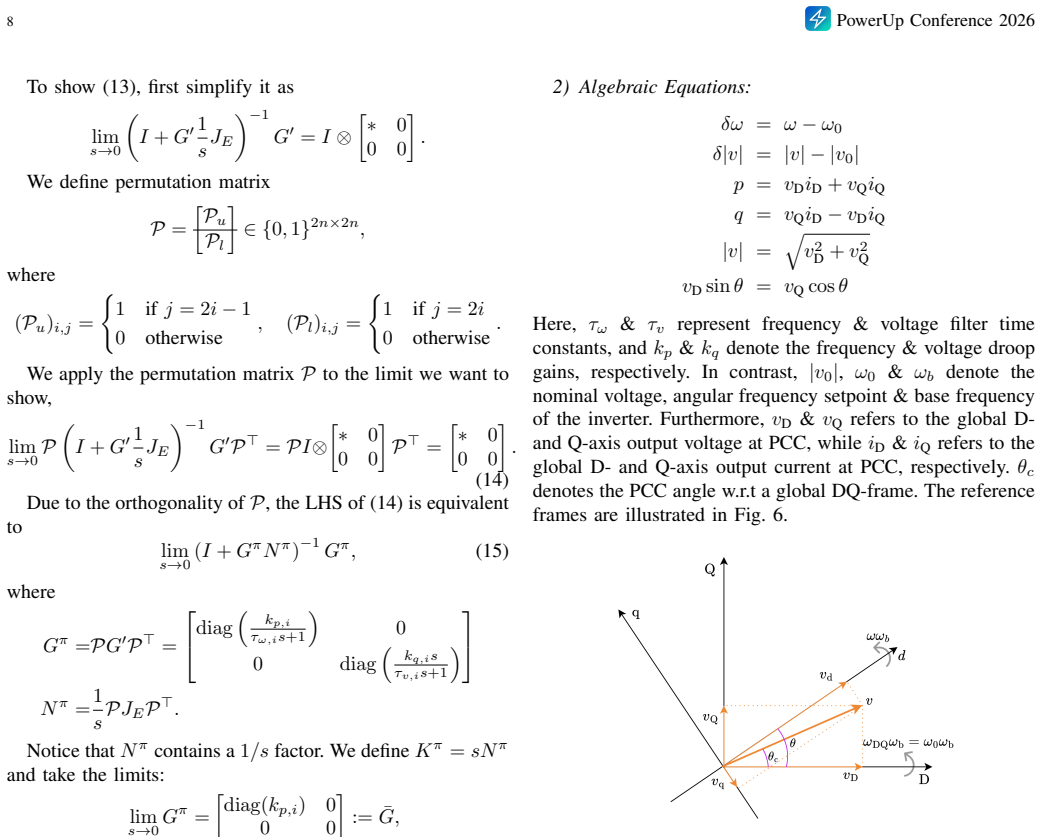
Differential Equations: ˙θ=ω bδω τω ˙δω=−δω+ (p ∗ −p)k p τv ˙δ|v|=−δ|v|+ (q ∗ −q)k q
-
[18]
In contrast,|v 0|,ω 0 &ω b denote the nominal voltage, angular frequency setpoint & base frequency of the inverter
Algebraic Equations: δω=ω−ω 0 δ|v|=|v| − |v 0| p=v DiD +v QiQ q=v QiD −v DiQ |v|= q v2 D +v 2 Q vD sinθ=v Q cosθ Here,τ ω &τ v represent frequency & voltage filter time constants, andk p &k q denote the frequency & voltage droop gains, respectively. In contrast,|v 0|,ω 0 &ω b denote the nominal voltage, angular frequency setpoint & base frequency of the i...
discussion (0)
Sign in with ORCID, Apple, or X to comment. Anyone can read and Pith papers without signing in.